
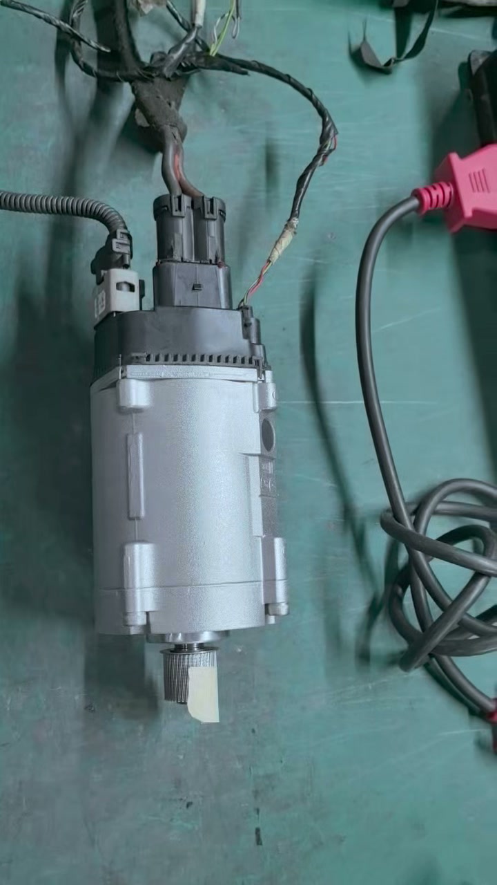
 Watch the BMW F30 EPS motor bench-test video (27.5 seconds)
The recording is available on a dedicated video watch page; the evidence analysis continues below.
How the recording confirms motor movement
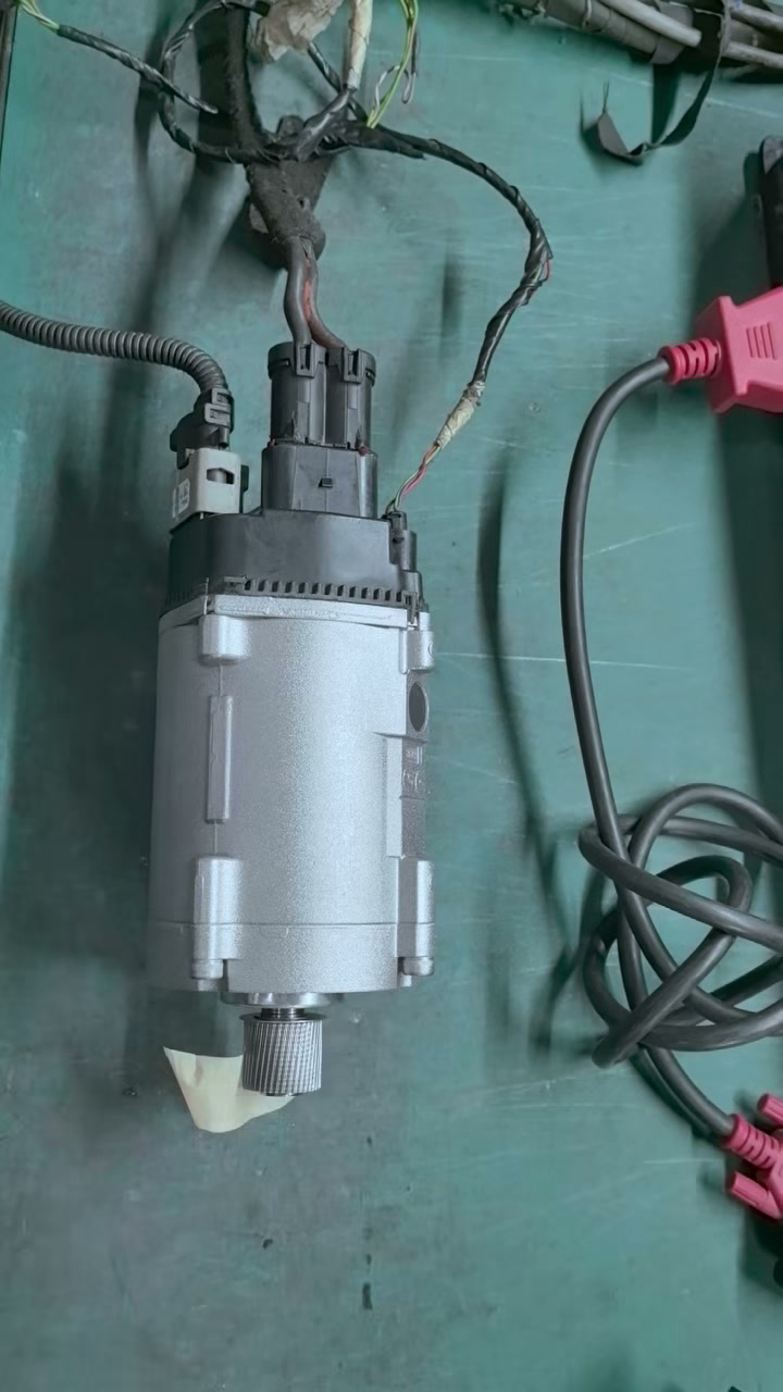
A light-colored tape marker was placed on the splined shaft as a visual reference. Its position changes between the recorded stages. That is enough to confirm angular movement in this setup without guessing a motor speed or output torque that was never measured on screen.
What the scanner data actually shows
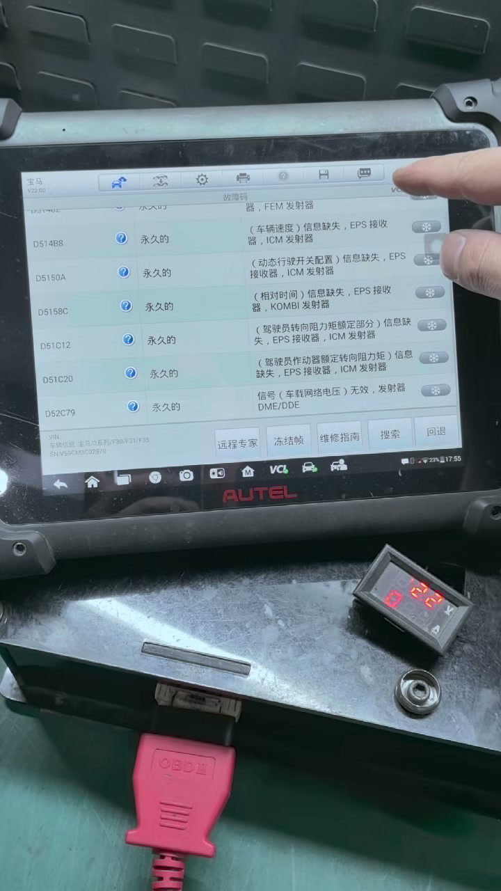
The scan-tool page in the video is a fault-code list. The following codes and shortened descriptions are readable; wording can differ between scan-tool software versions and translations.
| Visible DTC | Short description | Modules named on screen |
|---|---|---|
| D51488 | Vehicle-speed information missing | EPS receiver / ICM transmitter |
| D5150A | Dynamic-driving switch configuration missing | EPS receiver / ICM transmitter |
| D5158C | Relative-time information missing | EPS receiver / KOMBI transmitter |
| D51C12 | Requested steering-torque message missing | EPS receiver / ICM transmitter |
| D51C20 | Actuator or requested steering-torque message missing | EPS receiver / ICM transmitter |
| D52C79 | Vehicle electrical-system voltage signal invalid | DME/DDE transmitter |
What this test proves—and what it does not
| Finding | Supported by this recording? | Reason |
|---|---|---|
| The output shaft rotates during activation | Yes | The tape marker changes angular position. |
| The EPS can communicate with the scan tool | Partly | A module DTC page is shown, but the complete identification session is not recorded. |
| The motor produces rated torque under load | No | No defined load or torque measurement is visible. |
| Current draw is within specification | No | No supply-voltage or amperage trace is shown. |
| The complete rack is ready to install | No | Mechanical, electrical, coding and installed-vehicle checks remain. |
Checks still needed before the unit is approved
- Identity: verify the complete OE number and suffix, system manufacturer, hardware/software identifiers and exact vehicle application.
- Power supply: record starting voltage, minimum voltage during activation, ground quality and voltage drop at the motor.
- Current: measure draw at rest, during movement and against a defined load, using an agreed acceptance range.
- Direction and control: check smooth response in both directions, including stops, interruptions and repeatability.
- Physical behavior: record abnormal noise, vibration, connector condition and temperature rise over a defined cycle.
- Installed diagnosis: identify the module, clear and re-read DTCs, check available live data, then perform the required BMW/ISTA programming or end-stop learning for the specific vehicle.
A defensible test conclusion
For this recording, the accurate conclusion is: the EPS motor produces visible shaft rotation when activated on the bench shown. The displayed faults mainly describe missing or invalid messages between vehicle modules and need to be checked again on the complete car. The video does not contain enough data to confirm loaded performance or the final condition of the entire steering rack.
Frequently asked questions
Does rotation mean the motor is good?
It confirms a basic response in these test conditions. Approval still requires electrical measurements, a defined load, both-direction operation and final diagnosis on the vehicle.
Do these DTCs mean there is an internal motor fault?
Not on their own. The visible descriptions concern messages from other modules. If the faults remain with the correct unit installed on a complete network, they must be diagnosed under the BMW procedure.
Is the computer showing live data?
No. The video shows stored DTC descriptions. Current, torque, angle, speed and temperature are not displayed as live values.